Tom Patterson, US National Park Service
This tutorial introduces techniques for manipulating Digital Elevation Models (DEMs) with BSmooth shareware. The techniques described here attempt to emulate the 3D presentation styles pioneered back in the twentieth century by two noteworthy traditional cartographers.
Richard Edes Harrison, who worked as an illustrator/cartographer for Fortune magazine during the post W.W.II years, inspired the first technique. Harrison's maps featured oblique over-the-horizon views, non-traditional orientations, and 3D relief that interrupted the curved horizon. Although Harrison's pieces were thought provoking and commercially popular, his techniques were looked upon with general disapproval by the cartographic establishment of the day. Nevertheless, a half century later, Harrison's maps are remembered fondly by many, while his detractors' works have largely been forgotten.
The second technique borrows from Heinrich Berann, the renowned panoramist and classical painter from Austria, who died in late 1999 at age 83. Berann would shape the projection plane on large-scale panoramas as a convex arc instead of a flat plane. This modification served to portray foreground topography in a readable map-like manner while background areas were shown in perspective with a natural-appearing horizon. It is not an overstatement to describe many of Berann's panoramas as masterpieces of 3D landscape visualization.
Although the artistic styles of Harrison and Berann were quite different, they shared uncommon artistic talent and a prescient understanding about the power and universal appeal of 3D presentation long before it came into vogue.
Technique 1 - How to make Harrison-style spherical horizons
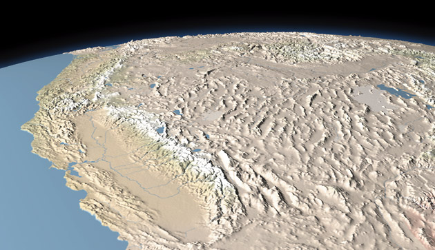
An over-the-horizon view of California and the western United States created from GTOPO30 elevation data modified with BSmooth shareware. Note that topography breaks the curved horizon, unlike bump mapping techniques. The scene was rendered in Bryce.
Overview
Most, but not all, software used for depicting 3D landscapes derived from Digital Elevation Models (DEMs) ignores the Earth's curvature, even at small scales. By ignoring the Earth's spherical shape, which is the most prominent 3D component of all, realism is diminished. This tutorial introduces a simple technique for merging DEMs and GTOPO30 onto spherical surfaces that resemble the Earth's surface. The resulting files can be exported to Bryce, Natural Scene Designer, World Construction Set, and, other popular 3D landscape rendering applications.
The technique described below depends on BSmooth, a graphical utility dedicated to creating, modifying, and exporting 3D objects with the ultra-smooth quality inherent in 16-bit data. In the case of DEMs or GTOPO30, BSmooth will export files containing over 63,000 levels of height information, compared to 256 levels available to 8-bit data. The end result are landscapes that render with exceptional detail and smoothness -- depending, of course, on the quality of the original DEM data.
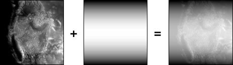
The procedure for merging a DEM onto a curve is straightforward. First, you open a raster DEM in BSmooth on a "Pixel Op" layer. The curved surface to be merged with the DEM is defined by a vector path saved in Adobe Illustrator format. The Adobe Illustrator path, which in this case is shaped like an arc, is then opened in BSmooth on an "Extrude Op" layer. By combining two Extrude Op layers, with the Illustrator arcs trending perpendicular to one another, a partial sphere is created that resembles the curvature of the Earth.
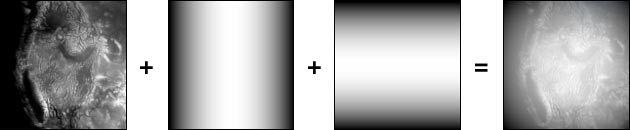
A raster DEM combined with two Adobe Illustrator arcs
created a domed DEM. White represents higher elevations.
Tutorial
Items you will need:
--A Macintosh with lots of RAM
--Free data: DEMs
or
GTOPO30
--BSmooth shareware (US$35)
--Adobe Photoshop
--Your favorite 3D software
Step 1 - Data preparation
Small-scale DEMs and GTOPO30 are more appropriate for making scenes that show the Earth's curved horizon. Whatever data you decide to use, it will need to be saved as a raster image, in either 8-bit grayscale Pict or 16-bit grayscale Photoshop format. Furthermore, the DEM must be formatted to one of the following quadratic file sizes (in pixels): 256 x 256, 512 x 512, 1024 x 1024, 2048 x 2048, 4096 x 4096, or 8192 x 8192. Note: In BSmooth, PICT files cannot exceed 2048 x 2048 pixels. Larger DEMs must be saved in 16-bit Photoshop format.
Click here for information about preparing GTOPO30 for use with Photoshop and BSmooth.
Click here
for information about preparing DEMs for use with Photoshop and BSmooth.
Step 2 - BSmooth setup
Once your DEM data is prepared to the specifications described above, the hard part is over. All that remains is loading the DEM in BSmooth, selecting a pre-made Adobe Illustrator arc, setting preferences, and clicking the "Go" button. Oh, there is one more thing. Make sure to pump up BSmooth's RAM allocation.
A) Launch BSmooth. Select the "Pixel Op" layer operation from the "Ops" tool bar (right side, third icon from top).
B) Load the DEM in the Pixel Op layer by clicking the "Default" label.
C) Click on the terrain size label in the "Go" layer. Set the terrain size to match the pixel dimensions of the DEM.
D) Select the "Extrude Op" layer from the "Ops" tool bar (the topmost icon, left side).
E) Click on the "Default" label in the Extrude Op layer. The open dialog appears. Go to the BSmooth folder on your hard drive (BSmooth/Example Files/Extrusion/Illustrator Files/Bow) and select the Adobe Illustrator file called "Bow."
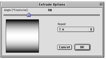
F) Repeat steps D and E to load a second Extrude Op layer containing "Bow." However, this time you will rotate the orientation of "Bow" 90 degrees. Click the icon on the left side of the new Extrude Op layer. In the "Extrude Options" dialog rotate the angle 90 degrees.
G) At this point you are almost finished except for setting the output preferences. Go to File/Preferences in the top drop menu. What you choose depends on the 3D software that will be used for rendering. The output options are:
--Bryce 2, 3, and 4: Good only for terrains 1024 x 1024 and smaller.
--PGM: Used only with Bryce 4 . Accepts file sizes larger than 2024 x 2024.
--DXF: A bloated and clunky format when used for topographic purposes, but nearly universal.
--16-bit Photoshop: A very useful format. It allows terrains to be opened in Photoshop and re-exported to other raster formats, such as Pict and Targa, that are readable by many 3D applications.
H) Click the "Go" button to export the final results.
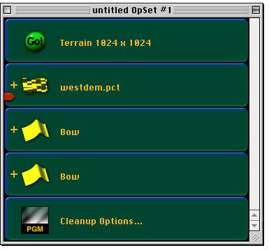
BSmooth setup to export GTOPO30 data that was used for
rendering the California scene at the beginning of the tutorial.
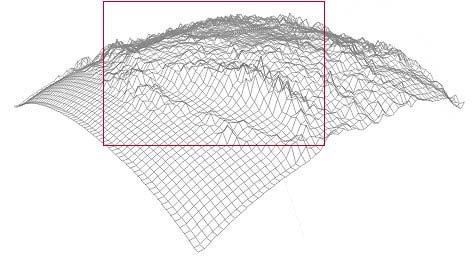
A wireframe view of the exported GTOPO30 as it appeared
in Bryce. The arced edges were hidden by carefully positioning the DEM
within Bryce's rendering window shown by the red box.
Step 3 - Fine tuning
When imported into a 3D program, the curved DEM appears much like a billowing square tarp staked over a ventilator shaft. The vertical exaggeration of topography and the curvature of the Earth are controlled by increasing or decreasing the vertical scale (Y axis) from within a 3D application. They cannot be adjusted independently of one another. For example, flattening the curvature of the Earth also flattens topography by a proportional amount. Fortunately, BSmooth provides tools for controlling the vertical exaggeration of the DEM relative to the spherical surface beneath it. Finding the perfect combination requires trial and error and may involve exporting several files at different settings. To adjust topographic height and curvature:
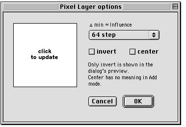
A) In BSmooth, click the icon on the left side of the "Pixel Op" layer. The "Pixel Layer" options dialog appears. In the pop-up menu change the step amount (64 is the default) to another value. Lower step values increases topographic prominence relative to spherical surface underneath, and vice versa. 16-bit DEMs require much lower settings than do 8-bit DEMs.
B) Adjusting step values is a coarse method for controlling relative heights. If greater refinement is needed, add an "Amplify Op" layer (Ops tool bar, right side, second icon from the bottom) to the layer stack. The Amplify Op multiplies the effect of the preceding layer by incremental amounts.
C) Click in BSmooth's main preview window to visually inspect
effects of the new settings before clicking the Go button.
Comments
The technique described above is not suited for depicting the entire Earth or even hemispheric views. When a DEM is warped to hemispheric proportions, the arced sides become too exaggerated and project into the image area, limiting formatting options within a rectangular frame. However, because of scale, hemispheric maps need not show mountains punctuating the horizon -- a smooth horizon looks tidier and matches the actual appearance of the Earth as seen from space. To better place topography on a globe (or part of a globe), in a 3D application, use spherical mapping mode, or a bump map texture generated from an alpha channel containing topographic height information, to wrap 2D shaded relief around an otherwise smooth sphere.
The horizon is smooth when 2D shaded relief is mapped,
like a decal, onto a sphere. Click here
for a larger image.
Technique 2 - How to make Berann-style panoramic bases
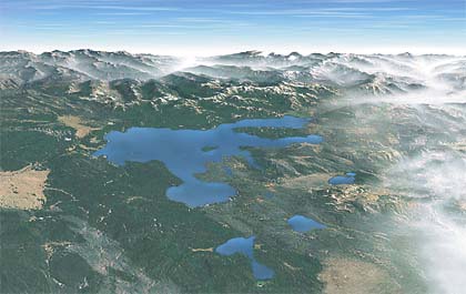
This view of Yellowstone Lake was created from a
Landsat image draped onto USGS DEMs and rendered in Bryce. Note how the
foreground appears more perpendicular to the viewer than the background
-- a visualization technique frequently used by panoramist Heinrich Berann.
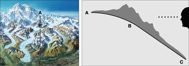
The left image shows a portion of Berann's traditional
panorama of Denali. The profiled illustration to the right depicts how
Berann modified the projection plane as a convex arc and tilted the foreground
toward the viewer. Click here
to see Berann's Denali panorama.
Using BSmooth, the technique for merging a DEM onto a
convex arc is similar to the technique for merging a DEM onto a sphere,
except that only one Adobe Illustrator arc is used. The arc needs to be
positioned perpendicular to the viewing direction -- a condition that must
be rigorously maintained after the convex DEM is imported with a 3D application.
Comments
1) Like the Harrison technique described above, the vertical exaggeration of topography and the amount of convexity cannot be adjusted independently. To give yourself design options, export several convex DEMs from BSmooth at variable settings (see Technique 1, Step 3).
2) When rendering 3D panoramic scenes, try diminishing perspective convergence. In Bryce this is done by adjusting Field of View (double click on the Camera Trackball for the dialog). The default value is 60, which pinches background areas too much. A value of 30 or 40 usually works best. Using a lower value widens background areas, making the entire scene easier to fit within the confines of a rectangular frame.
3) Positioning a convex DEM in Bryce can be tricky. Use the camera positioning tools in the usual manner. You will also need to rotate the DEM itself on the X axis to find the perfect balance between foreground detail and background flattening, adjusting the overall size of the terrain (x, y, and z axis) and vertical exaggeration (Y axis) as you go. When positioned correctly, the back edge of the convex DEM should be slightly higher than the horizon. In applications such as Natural Scene Designer and World Construction Set, where terrain cannot be moved, setting up a scene is a simple matter of adjusting vertical exaggeration and positioning the camera.
Click here to download pre-configured BSmooth documents for creating the techniques described above (194k).