Tom Patterson, US National Park Service
Update 1: I now prefer calling the technique described in this tutorial "plan oblique relief" rather than "3D planimetric relief."
Update 2: For more information about plan oblique relief and to download a map of the coterminous United States made with this technique visit: www.shadedrelief.com/physical.
Update 3: Natural Scene Designer Pro 5.0 (due for release spring 2007) renders plan oblique relief from DEMs much more easily and with higher quality and accuracy than the technique described below.
Introduction
This tutorial introduces a technique using Bryce and Photoshop software
to bring the 3D terrain depiction found on panoramas to ordinary
planimetric (flat) maps. The technique gives cartographers an
alternative to traditional shaded relief for presenting terrain at
small-scales (Figure 1).
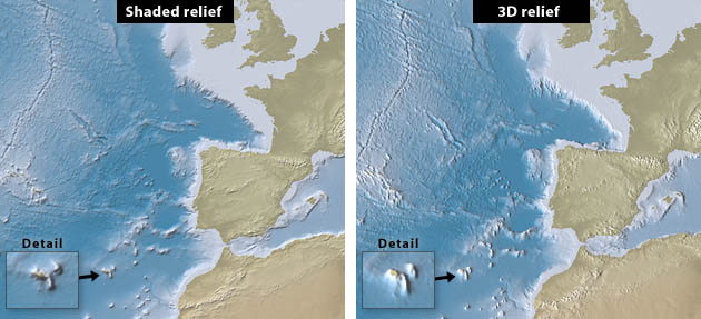
Figure 1. Planimetric maps in the Albers Equal-Area Conic Projection
shown with traditional shaded relief and 3D relief. Illumination
emanates from the northwest on the shaded relief and from the southwest
on the 3D relief, the optimal illumination direction for each method of
relief portrayal.
Compared to shaded relief, which assumes a theoretical viewpoint
directly above the earth, 3D relief shows landforms “standing up” in
partial profile. Because 3D relief closely resembles how mountains
appear to humans on the surface of earth, it is easier for people to
understand at a glance. High solitary mountains, such as Mt. Fuji and
Mt. Kilimanjaro, which are all but invisible on a shaded relief map
from above, actually look like the spectacular mountains that they are
when viewed obliquely in 3D.
The early popularity of 3D relief portrayal on maps is not surprising—it is easy to create and easy to understand. Even today, given a blank outline map and the assignment to depict the Andes, most people would fill the western edge of South America with a row of symbols that look like inverted V’s. As primitive as this style may be, it nevertheless gives a better pictorial representation of Andean volcanoes at small-scale than more accepted forms of cartographic relief depiction, such as contours, hypsometric tints, and shaded relief.
Despite the advantages of 3D planimetric relief, it is rare today. During the last two centuries as cartography became a formal profession, 3D relief has fallen out of vogue in favor of more scientific and accurate methods of relief portrayal. The technique does indeed have its shortcomings. Because 3D relief shows only the south-facing slopes of prominent topographic features (on north-oriented maps), information is lost. This problem is most critical at large scales rather than small. Not seeing the north facing slopes of, say, the Grand Canyon on a 1: 5,000,000-scale map is not a major issue—at such small scales hidden areas comprise only a tiny percentage of the entire map and understanding the overall topography of the Colorado Plateau is a design priority. By contrast, at larger scales areas hidden by 3D relief can account for a much higher percentage of the total map area. Hiking the Grand Canyon with a 1:25,000-scale map that does not show the cliffy slopes below the South Rim would not do. Furthermore, 3D relief conceals the glaciated north faces of high mountains in the northern hemisphere, which are usually the most dramatic and recognizable.
Another shortcoming of 3D relief presented on large-scale planimetric maps is one of confused identity. As neither a panorama nor map, these products simply don’t look right. At large scales one expects to see evidence of perspective—background haze or terrain diminishing in size with distance—that is not present. Fortunately, for our purposes, at smaller scales our eyes are accepting of this hybridized depiction.
On small-scale planimetric maps 3D relief depiction is best suited to physical base maps with minimal line work and thematic information. A map showing the meandering route of a traveler through various countries would be an appropriate use. The technique excels at showing physiography. During the mid twentieth century, Erwin Raisz of the US and Heinrich Berann of Austria, with their famous and widely differing styles, used 3D planimetric relief with great success to present topography on small-scale physical maps (Figure 2).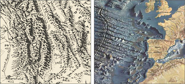
Figure 2. Examples of 3D planimetric relief. (left) A physiographic map of southern California inked by Erwin Raisz. (right) An ocean floor map painted by Heinrich Berann in 1968. Note that Raisz uses lower left illumination and Berann’s illumination originates from the lower right.
Today, 3D planimetric relief is perhaps most common on the decorative (and sometimes fanciful) reference maps found in books on travel, history, and popular fiction. Reading a popular travelogue containing simple but effective maps with 3D planimetric relief compelled me to investigate this technique. Practioners of this mapping niche, which includes many non-cartographers, still largely draw 3D relief by hand. This is partly because of the desirable graphical ambience that manual relief provides, and partly for lack of appropriate automated tools. As far as I know, no software available today produces 3D planimetric relief as a standard feature. Seeking to fill this void, I turned to my favorite applications, Bryce and Photoshop.
Tutorial
My procedure—a workaround, actually—involves two series of steps. The first steps use Bryce to render a base map derived from elevation data as a typical perspective scene with 3D topography. The second steps use Photoshop to transform the perspective scene rendered in Bryce back to its original 2D shape (Figure 3, left). Doing this restores the planimetric characteristics of the base map while retaining the 3D appearance of the topography rendered in Bryce (Figure 3, right).

Figure 3. (left) Transforming a 2D image of a perspective map back to its original planimetric shape (in this case a square) by repositioning the corners in Photoshop. (right) The transformed results.
Now that you understand the gist of the procedure, I must confess to a major problem with the example shown in Figure 3. Because of the extreme foreground pinching, background stretching, and resizing, the transformed image would have a degraded quality unsuitable for mapping. Pixels will stretch only so far. However, by changing the procedure slightly you do not have to compromise quality. Rendering the 3D scene in Bryce with almost no perspective and very close to its original size and square shape minimizes the need for destructive transformations, thus preserving the image quality. The step-by-step instructions that follow explain how to do this.
For this tutorial you will need Adobe Photoshop, Bryce 5, basic proficiency in both software applications, and a chunk of small-scale 16-bit elevation data in PGM format.
To download the data used in Figure 3 click here (2.3MB). Usable by Mac or PC, the data consists of a downsampled 1024 x 1024 PGM DEM derived from ETOPO2 and registered bathymetric tints, which you can drape on the DEM as an option.
Bryce procedure
Shortcut: The Bryce setup file downloadable here (4KB) allows you to bypass steps 1-5 below. Windows users need to add a ".br5" extension to the file name to open it in Bryce 5.
1) Launch Bryce.
2) In the Document Setup dialog (File/Document Setup) deselect the Constrain Proportions button and set the Document Resolution (which determines the size) to a square shape that fits entirely on your monitor.
3) Select and delete the default plane in the Bryce scene.
4) In the Sky and Fog palette:
A. Select Simple Black Background as the sky color.
B. Change the Shadows setting from 90 to 0 to eliminate cast shadows
from the scene.
5) Double click the large Camera Trackball and set the FOV (Field of View) setting to 1, the lowest value possible. Doing this removes most of the perspective from the Bryce scene. It also makes objects in the scene appear much larger, so you will need to repeatedly push back on the Z dimension using the XZ Camera Control arrow until the entire scene fits inside the square Bryce document window.
6) Go to File/Import Object and import a square PGM terrain and use the Camera Trackball to orient the terrain north and set the viewing elevation. It should appear similar to the foreshortened terrain shown in Figure 4, left.
Note: The Bryce setup file I provide automatically orients imported PGM terrains to the north (assuming that they are north oriented to begin with) and sets the viewing elevation to produce 3D terrain that “looks right” at small map scales.
7) To stretch the foreshortened terrain into a square, select the
terrain and click the small A near the lower right corner of the
terrain. The Object Attributes dialog then appears (Figure 4, right).
Enter a Z value approximately twice that of the X. Use the square Bryce
document window as a visual reference for determining when the terrain
has become nearly square. It doesn’t have to be perfect.
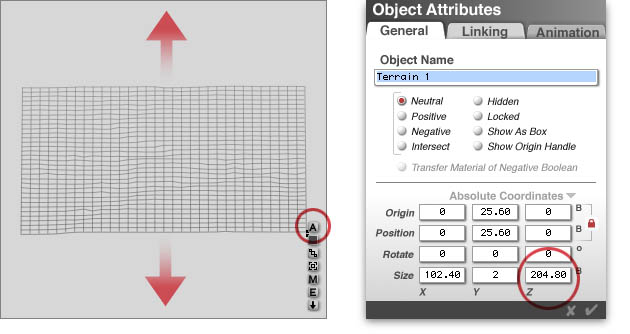
8) While in the Object Attributes dialog, you should also adjust the vertical exaggeration of the terrain by entering a value in the Y field at the bottom of the dialog. Choosing the amount of vertical exaggeration is a subjective decision. However, when in doubt always go with less. For the sample data a value of 2 worked well.
9) Render the scene and save the image in Photoshop format.
Photoshop procedure
1) In Photoshop, open the image of the perspective terrain you just
rendered in Bryce.
2) Go to Image/Canvas Size and increase the canvas size by 120% on all sides. The extra space will give you maneuvering room later when you transform the image.
3) You will need two layers in Photoshop. Place the rendered Bryce terrain on the top layer. Lessen the opacity and/or change the blending mode of the top layer in order to see through to the layer below.
4) On the bottom layer place the original square map before it was rendered in perspective in Bryce. If this is unavailable, any square filled with a flat color will do (see Figure 3, left). Size the square as close as possible to that of the Bryce image above.
5) On the top layer, use the Rectangular Marquis Tool to draw a selection over the entire perspective terrain. Include a little extra space on all four sides.
6) Select Edit/Free Transform from the top drop menu and adjust the size and shape of the perspective Bryce scene to register with the square below. Because the top and bottom edges of the Bryce terrain are crenellated by topography, the straight left and right sides of the Bryce terrain are a better alignment guide.
Tip: Holding down the Command key (Mac)/ Control key (PC) and click-dragging the any of the corners of the transformation box permits non-rectilinear distortions to the image.
7) Double click inside the transformation box to apply the
transformation. The transformed Bryce terrain should now exhibit the
planimetric characteristics and 3D topography.
Miscellaneous Tips
Perspective depth: Unlike panoramas, on 3D planimetric maps adding atmospheric haze or diminishing the width of linework in background areas is inappropriate because foreground and background areas don’t exist on these maps.
Aerial perspective effect: Valley haze used to differentiate lowland from highland areas is appropriate to show on 3D planimetric maps. A height mask rendered separately in Bryce is essential for applying this effect. To use height mask you must transform it to exactly the same planimetric shape as the 3D relief. You do this by recording the transformation applied to the 3D relief as a Photoshop Action and replaying it to transform the height mask.
Lighting: Standard northwest illumination used with traditional shaded relief does not apply to 3D planimetric relief because it places deep shadows on slopes facing the viewer. Lighting on 3D planimetric relief should originate from the lower left or right similar to the lighting used on panoramas and depending on how the topography trends. If everything else is equal, use lower left illumination because it is closer to the cartographic standard.
Mountains needed: 3D planimetric relief works best for maps containing high relative relief. On gentler terrain 3D relief looks too similar to shaded relief, which results in confusion.
Sharpening: If background (top) areas look fuzzy after applying Photoshop transformations, correct it by selectively applying the Unsharp Mask filter. I prefer to create two layers in Photoshop with copies of the 3D relief on each. I then apply an appropriate amount of Unsharp Mask to the relief on the bottom layer. Finally, on the top layer I add a layer mask and fill it with a linear gradient (applied from bottom to top), which allows sharpened terrain at the top to show through.
Resolution bumping: Vertical exaggeration applied to
small-scale elevation data causes tall solitary peaks on 3D relief to
spike upwards in an unsightly manner. Using a DEM manipulation
technique in Photoshop called resolution bumping before rendering the
DEM in Bryce lessens this problem. To learn more about the resolution
bumping technique click here.
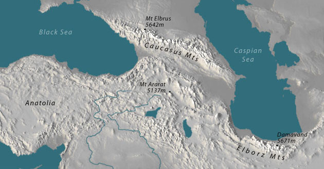
Figure 5. Resolution bumping allows the application of
substantial vertical exaggeration to 3D planimetric relief. Without the
application of resolution bumping on this map Mt. Ararat would appear
as a tall spire.
Linework:
Creating a map with 3D planimetric relief map takes more time than
making one with traditional shaded relief. Dealing with linework
contributes greatly to the additional time. Linework on 3D planimetric
maps interacts with topography in the same manner as on panoramas: it
goes up and down. For example, a political boundary following the crest
of a mountain range would rise and fall with the mountains and
occasionally disappear into deep valleys. To accurately plot lines
requires draping lines on the 3D topography in Bryce and creating a
separate render with only lines for compositing in Photoshop
afterwards. A possible exception to this approach is the graticule that
could overlay the map without interacting with topography.
Getting creative: The techniques covered so far yield 3D
relief that is accurate and looks competent, but lacks artistic style.
To give your relief a painterly look experiment with the artistic
filters in Photoshop in combination with one another (Figure 6). If the
effect of a particular filter appears excessive even at the lowest
settings possible, using the Fade command (Edit/Fade) after applying
the filter gives finer control over how it looks compared to the
original image.
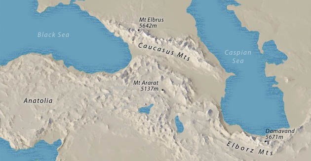
Figure 6. Two-minute map art made with the Dry Brush, Find Edges and Graphic Pen filters in Photoshop.
Return to Shaded Relief home