Tom Patterson, US National Park Service
Terrains rendered in Bryce by default appear as
floating landscapes, much like a flying carpet, without the extruded block
bases that cartographers have traditionally used to portray 3D landscapes,
particularly geologic diagrams and oblique designer maps intended for use
in popular publications. In this tutorial I describe techniques in Bryce
for presenting DEMs on 3D block bases and extruding geographic shapes,
such as country outlines, as slabs.
Smoke and mirrorshow it works
The key to the technique is boolean rendering. Simply explained, any object in Bryce can be used to add or subtract itself from other objects, providing that they overlap. Changing an object's boolean attribute to neutral, positive, negative, or intersect, determines how it will interact with other objects when rendered.
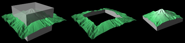
The images below illustrate basic boolean rendering.
The left image shows a cube intersecting a DEM of Mt. Hood, Oregon. Both
objects have neutral attributes, so they render as visible entities in
the normal Brycean fashion. The middle image was created from the same
data as the first image. In this case, however, the boolean attribute of
the DEM was changed to positive and the cube to negative, which subtracts
the square from the DEM. The right image, depicting a traditional block
diagram, was rendered with the boolean attribute of the DEM set to positive
and the cube to intersect.
Boolean rendering is unique in that the affected objects are not altered structurally, despite the dramatic change in their appearance when rendered. This allows for unlimited editing opportunities. Refering to the illustration above, the cube could be deleted, resized, or converted to another primitive object, say, a sphere, without damaging the underlying DEM of Mt. Hood.
Another powerful characteristic of boolean rendering
is the ability to transfer the material properties of an intersecting or
negative object to the positive object that it clips. This includes color,
draped pictures, bump mapped textures, transparency, reflectivity, and
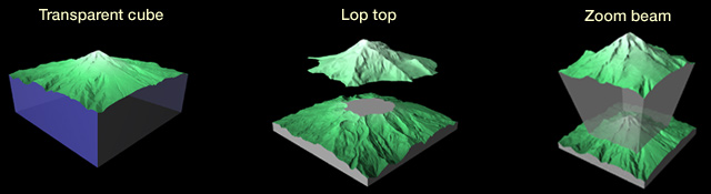
the other esoterica found in Bryce's materials editor. In the examples
below, the transparent cube was created by intersecting the DEM with, well,
a transparent blue cube.
Boolean rendering examples (no Photoshop touchup was used)
Technique 1: Making basic block bases
1) Initial setup: Launch Bryce and delete the default infinite plane that appears with the new file. Since atmospheric effects are not needed with block diagrams, I usually choose a simple black or white background from the sky presets. In the sky palette set the shadow value to zero.
2) Import a DEM or create a randomized fractal terrain by clicking on the terrain icon in the create palette. Either way, the remaining steps apply identically to any terrain object in Bryce regardless of its origins.
3) If you render the terrain now it will appear without a base. Bryce internally calculates terrain heights with 16-bit vertical resolution starting at the lowest elevation on the surface and ending at the highest. To create a block base you need to redistribute a portion of the vertical data below the lowest elevation on the surface. Don't worry about degrading the terrain. This is like giving blood--with over 64,000 levels of available height information you can easily afford to make a donation.
With your terrain selected, enter the terrain editor. Find the "Dampen" button on the elevation tab (left image below) and click-drag it to the left. Be careful, if you drag too far the terrain will invert itself. You want to flatten the terrain just a little, which in effect transfers height data downward. The middle and right images below show a typical terrain before and after dampening. Exit the terrain editor.
4) After dampening, the wireframe terrain also appears flattened. In the edit palette use the resize widget to increase the vertical exaggeration (Y axis) to a more appropriate amount. You may also need to lower the position of the terrain inside Bryce's rendering window using the reposition widget (use the Y axis again).
5) Now for the tricky part:
a. When any object is selected in Bryce, a small contextual menu appears to the lower right of the bounding box (see the illustration below) providing shortcuts to various editing functions ("M" represents the materials editor and "E" the terrain editor). Click the "A" to open the object attributes dialog.
b. In the object attributes dialog click the "Positive" radio button to change the boolean rendering attribute to positive (neutral is the default). Exit the object attributes palette.
c. With the terrain still selected, duplicate the terrain in place (Edit drop menu/Duplicate or Command-D).
d. The duplicated terrain will be used to create a cube. In the edit palette look for the small double arrow at the upper right (see the illustration below). Clicking on it brings up a menu of objects; select the cube. The duplicated terrain then changes to a cube with the same dimensions and material properties as the terrain it replaced.
e. In the materials presets, change the color of the cube to a simple flat color different from the terrain.
f. With the cube selected, click on the "A" shortcut to open the objects attributes dialog again. Click on the "Intersect" radio button. While in the objects attributes palette you must diminish slightly the x and z dimensions of the cube so that it clips the sides of terrain when rendered. In the example below, I changed the X and Z sizes from 81.9 to 81.0. I also doubled the Y size to prevent the top of the cube from truncating the terrain. Exit the object attributes palette.
6) You are almost finished. Objects need to be grouped for boolean rendering to work. Select the cube and terrain (Edit drop menu/Select All or Command-A) and group the objects by clicking the small "G" that appears in the contextual shortcut menu. (When objects are grouped the "G" toggles to "U" for ungroup).
7) Render the scene. A cubic base should appear
at the bottom of the terrain.
Suggestions:
--Objects within groups can be selected directly without ungrouping. Use the selection palette below the main Bryce rendering window. (It shares common space with the animation palette. If necessary, click on the peculiar grid-like icon at the extreme lower right of Bryce's window to toggle between the palettes). In the selection palette, simply click on the icon for the object type you want to select.
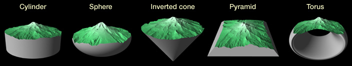
--Try substituting other primitive objects, such as a sphere or pyramid, for the cube. Use the steps described in 5.d. above to swap objects.
--Intersecting objects can be repositioned, rotated, or rescaled.
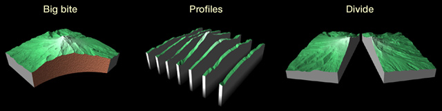
--Multiple intersecting and negative objects, in any combination, can be used to clip a positive terrain.
--Raising the lower limb of the clipping bracket in the terrain editor diminishes the thickness of a block base. This can also be accomplished by raising the lower edge of the intersecting cube with the resize widget in the edit palette.
The procedure
This procedure follows the same steps described
in the preceding section, except that a geographic shape is used as a boolean
intersect object instead of a cube. Preparing a geographic shape for use
in Bryce requires initial setup with a vector drawing program and
BSmooth
shareware.
Procedure:
1) In your favorite drawing program place a geographic shape within a square bounding box. Generalized shapes with fewer anchor points work best. Note in the illustration above that the Gulf of Mexico and Atlantic coast barrier islands were omitted.
2) While still in your drawing software, draw a path like the red lines shown in the illustration below. It must be constructed as a single path, with three anchor points, and a right angle. Snap it to the lower left corner of the bounding box as shown. The length of the two limbs does not matter, nor do the stroke and fill attributes. The path will serve as an extrusion profile when the file is processed next in BSmooth. Save the file in Adobe Illustrator format, preferably as version 6 or older.
Before moving on, a few words about the square bounding box. Remember that Bryce uses square-shaped terrains exclusively. If you are using a DEM in conjunction with a geographic shape, the outer margins of the DEM will automatically register with the bounding box. Be extra careful, however, that the geographic shape within the bounding box is in register with the internal DEM data. The same rule applies to draped images.
3) Launch BSmooth. In the Ops toolbar click the "Sweeping" icon (upper rightlook for the icon with a recessed S). This opens a default Sweeping operation set, which is used for extruding 2D Illustrator files into 3D objects (technically they are terrains) for export to Bryce (see the illustration below). Click on the "default" label on the middle layer of the OpSet to import your Adobe Illustrator file saved earlier. In the example below, the imported Illustrator file is called "usa.AI."
4) Click on the terrain size label (top layer) to adjust the terrain size. If you intend to use the extruded shape with a DEM in Bryce, the size of the extruded shape must match the size of the DEM. Otherwise 1024 x 1024 usually works well.
5) Click on the yellow Sweeping icon on the middle layer. This brings up the Seeping options dialog for setting the number of lines per curve. If you have a complex shape use a lower setting to speed up processing. As you will find out, sweeping operations in BSmooth are VERY slow!
6) Click on the "GO" button. BSmooth will extrude the shape as a Bryce terrain. This can then be used for clipping DEMs and other objects in Bryce.
Suggestions:
--Extruded shapes created in BSmooth tilt very slightly inward at the top. This is usually not noticeable in Bryce. However, the sides of shapes can be made to appear more vertical by excessively exaggerating the vertical size and using the bottom portion of the extruded shape to intersect the terrain.
--When rendered, the sides of the clipped terrain may show slight blemishes. They can be minimized by selecting the extruded shape, going to the terrain editor, and clicking the smooth button a couple of times. Be careful, however; too much smoothing causes sharp edges to become rounded. An easier solution would be to apply a bumpy texture to the sides of the extruded objectif appropriate for your project design.